Magnetic ignition system
The common magnetic ignition system has been around for over 100 years and can still used today in many stationary and small engines where size restrictions limit the use of external batteries. Magneto ignition system simple diagram It can used in many performance, aircraft and racing engines where a highly reliable, super-hot spark can required.
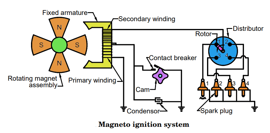
It differs from a conventional distributor in that it generates its own spark energy without an external voltage. A series of rotating magnets creates an electric field, which generates electricity in the primary windings of the coil. This current is amplified when the charge can transferred to the secondary winding of the coil. Because the number of windings in the secondary circuit is many times more than the primary circuit. This multiplying charge creates the magnet at a higher voltage than the voltage developed by the primary winding. In some cases, the voltage can be as high as 20,000 volts – resulting in a much hotter spark than conventional distributors.
Magneto ignition system simple diagram
traveling in a cam lobe, act like contacts in conventional distributors, controlling the electrical impulse to set the timing. Magneto ignition system simple diagram The points act as a barrier to the magnetic circuit, allowing a certain amount of charge to enter the secondary coil circuit, and a capacitor acts as a ground to dissipate the primary’s magnetic charge until the next armature cycle. The quality of the spark voltage improves as the engine speed increases as the magnetos spin faster and the primary winding energizes more frequently.
In single-cylinder engines such as lawnmowers or chainsaws, the spark plug wire can connected directly to the coil. In multi-cylinder engines such as tractors, motorcycles or cars, the magneto assembly can housed in a camshaft-driven housing and a rotor and magneto cover transmits voltage to the appropriate cylinder via metal spark plug wires. Magneto ignition system simple diagram Using a spark plug without resistance will produce a hotter spark.
The voltage generated by these magnets makes them ideal for track racers and cars that run on modified fuels such as alcohol or nitrous.
Working principle of magneto ignition system
There can two basic types of magnetic induction; The earliest version a self-contained unit with a coil mounted inside the housing, manufactured in the early 1900s. Magneto ignition system simple diagram A second type of magnet uses a battery-powered external coil. The most common external coil magneto in early cars was on the Ford Model T. Newer versions of both types of magnets are available from companies such as Taylor-Vertex, Harman-Collins, Mallory, and MST. Rare earth magnetic units are very popular today for their reliability.
As with a conventional point distributor, timing is important when using a magneto because there is no advance time to allow the engine to start easily and the advance time needed to make the magneto work at its peak at high rpm. For this reason, many modern aftermarket magnetos include a 12-degree mechanical advance, which allows the magneto to operate during start-up and when the engine is under extreme conditions. Magneto ignition system simple diagram More than 100 years after magnets were first designed, they can still manufactured for motorcycle, performance and classic car applications.
Principle of magneto ignition system
Magneto, a special type of machine-driven alternating current (AC) generator, uses a permanent magnet as a power source. Using the permanent magnet (the original magnetic field), Magneto ignition system simple diagram the coil of wire (the concentrated length of the conductor) and the relative motion of the magnetic field, current can produced in the wire. First, a magnetic machine generates electricity by rotating a permanent magnet and passing current through the coil winding. When current flows through the coil, it creates its own magnetic field around the coil.
At the right time, this current flow stops and the magnetic field collapses on the second set of windings in the coil and a high voltage current can generated. This can the voltage used to cause an arc across the spark plug gap. In both cases, there can three basic things needed to generate the electrical power to generate the high voltage that causes a spark to jump across the spark plug gap in each cylinder. Magneto ignition system simple diagram The magneto movement can timed to the engine so that the spark only occurs when the piston can on the correct stroke a certain number of crankshaft degrees before the top dead center piston position.
Magnetic ignition system components
Principle of operation of high pressure magnetic system
A high pressure magnetic system can, for the purpose of discussion, divided into three separate circuits:
Magneto ignition system simple diagram the magnetic, primary electrical, and secondary electrical circuits.
The magnet can attached to the aircraft engine and rotates in the space between the two pole shoes to provide the magnetic lines (flux) required to generate the electrical voltage. The poles of the magnet an arranged in alternating polarity so that the flux flows from the north pole through the coil core and back to the south pole of the magnet. Magneto ignition system simple diagram When the magnet can in the position the number of magnetic lines of force through the coil core can maximum because the two magnetically opposite poles can perfectly aligned with the pole shoe.
This position of the rotating magnet can called the full registration position and produces the maximum number of magnetic lines of force, clockwise flux through the magnetic circuit and left to right through the coil core. As the magnet can moved away from the full register position, the amount of flux passing through the coil core begins to decrease. Magneto ignition system simple diagram This happens because the poles of the magnet move away from the pole shoes and some flux lines take a short path at the ends of the pole shoes.
Magnetic system
As the magnet moves past the full register position, more lines of flux through the pole shoe ends become shorter. Finally, at 45° from full log position to neutral position, all flux lines become short circuits, and any flux flows through the coil core. Magneto ignition system simple diagram As the magnet moves from full register to the neutral position, the number of flux lines through the coil core decreases, just as the flux in the magnetic field of an ordinary electromagnet decreases.
The neutral position of a magnet is when one pole of the magnet can centered between the pole shoes of the magnetic circuit. As the magnet can rotated clockwise from this position, the flux lines short-circuited through the pole shoe ends again begin to flow through the coil core. But this time, the flux lines flow in the opposite direction from the coil core. Magneto ignition system simple diagram As the magnet leaves the neutral position, the flux flow reverses because the north pole of the rotating permanent magnet is opposite the right pole shoe instead of the left pole.
When the magnet rotates again through a total of 90°, another full log position can reached with maximum flux flow in the opposite direction. A 90° magnet travel 2, where a curve shows how the flux density in the coil core changes as the magnet rotates, without the primary coil around the core.
Primary circuit
A primary circuit breaker consists of a set of contact points, a capacitor and an insulated coil. The coil can made up of a few turns of heavy copper wire, one end of which can connected to the coil core and the other end to the ground portion of the breaker points. Magneto ignition system simple diagram The primary circuit can completed only when the ungrounded breaker point makes contact with the grounded breaker point. The third unit of the circuit, the capacitor (capacitor), can wired in parallel to the breaker points. When the circuit can opened the capacitor prevents currents from developing at those points and accelerates the collapse of the magnetic field about the primary coil.
The main breaker closes in almost full recording position. Magneto ignition system simple diagram When the breaker points close, the primary circuit is complete and the rotating magnet induces current flow in the primary circuit. This current flow creates its own magnetic field, which is in a direction that opposes any change in the magnetic flux of the permanent magnet circuit.
When induced current flows in the primary circuit, it opposes the decrease in magnetic flux in the core. Magneto ignition system simple diagram The primary circuit keeps the flux in the core at a high value in one direction until the rotating magnet has time to rotate a few degrees beyond the neutral position. This situation can called E-gap situation (E stands for efficiency).
Read More>>>> What is the working principle of spring hammer
Operation of high pressure magnetic system
Very high rates of flux change can achieved by opening the primary breaker points, with the magnetic rotor in the E-gap position and the primary coil holding the magnetic field of the magnetic circuit in opposite polarity.
Opening the breaker points stops the current in the primary circuit and allows the magnetic rotor to quickly change the field through the coil core. This sudden flux reversal produces a large flux change in the core, which shears the secondary coil of the magnet (wound and insulated from the primary coil), thereby inducing a high-voltage electrical pulse in the secondary. Magneto ignition system simple diagram When the rotor rotates almost to the full register position, the primary breaker points close again and the cycle can repeated to fire the next spark plug in the firing sequence. We can now review the sequence of events in more detail to explain how a state of extreme magnetic tension arises.
The breaker point, cam and capacitor can connected in circuit, the action that occurs when the magnetic rotor rotates can represented by the diagram curve. The top the original static flux curve of the magnets. The sequence of opening and closing magneto breaker points can shown below the steady flow curve. Note that the opening and closing time of the breaker point can determined by the breaker cam.
Magneto ignition system simple diagram The points can closed when the maximum amount of flux passes through the coil core and open at a position after neutral. As the cam has four lobes, the breaker points close and open in equal contact with each of the four neutral positions of the rotor magnet. Also, the intervals of point opening and point closing are almost equal.


