working principle of electro-pneumatic positioner
A valve positioner is a device used to increase or decrease air load pressure that drives an actuator until the valve stem reaches an equilibrium “position” for output signals from the process variable instrument controller. working principle of electro-pneumatic positioner
Valve positioners are used to control valves that require precise and fast control without error or hysteresis.
Positioners are usually mounted on the side or top cover of the pneumatic actuator for linear sliding stem control valves and at/near the end of the stem for rotary control valves. For any basic design type, a “mechanical feedback link” connected directly to the valve stem provides feedback to the controller. working principle of electro-pneumatic positioner The process controller tells the stabilizer to “change” state; A feedback link confirms that a change has occurred and informs the stabilizer that it “senses” the magnitude of the change in state.
How does an electropneumatic positioner work?
- Motherboard with microcontroller and input circuits
- Control panel with display and pushbuttons
- Piezoelectric valve unit, always present
- The valve unit is an accessory in the double-acting positioner
- Iy module for SIPART PS2 controller
- Alarm module for 3 alarm outputs and one binary input
- SIA module (slot initiator alarm module, Fig.) or mechanical
- Limit Switch Module
- Spring-loaded pneumatic actuator (single-acting)
- Springless Pneumatic Actuator (Double Acting)
Principle of operation
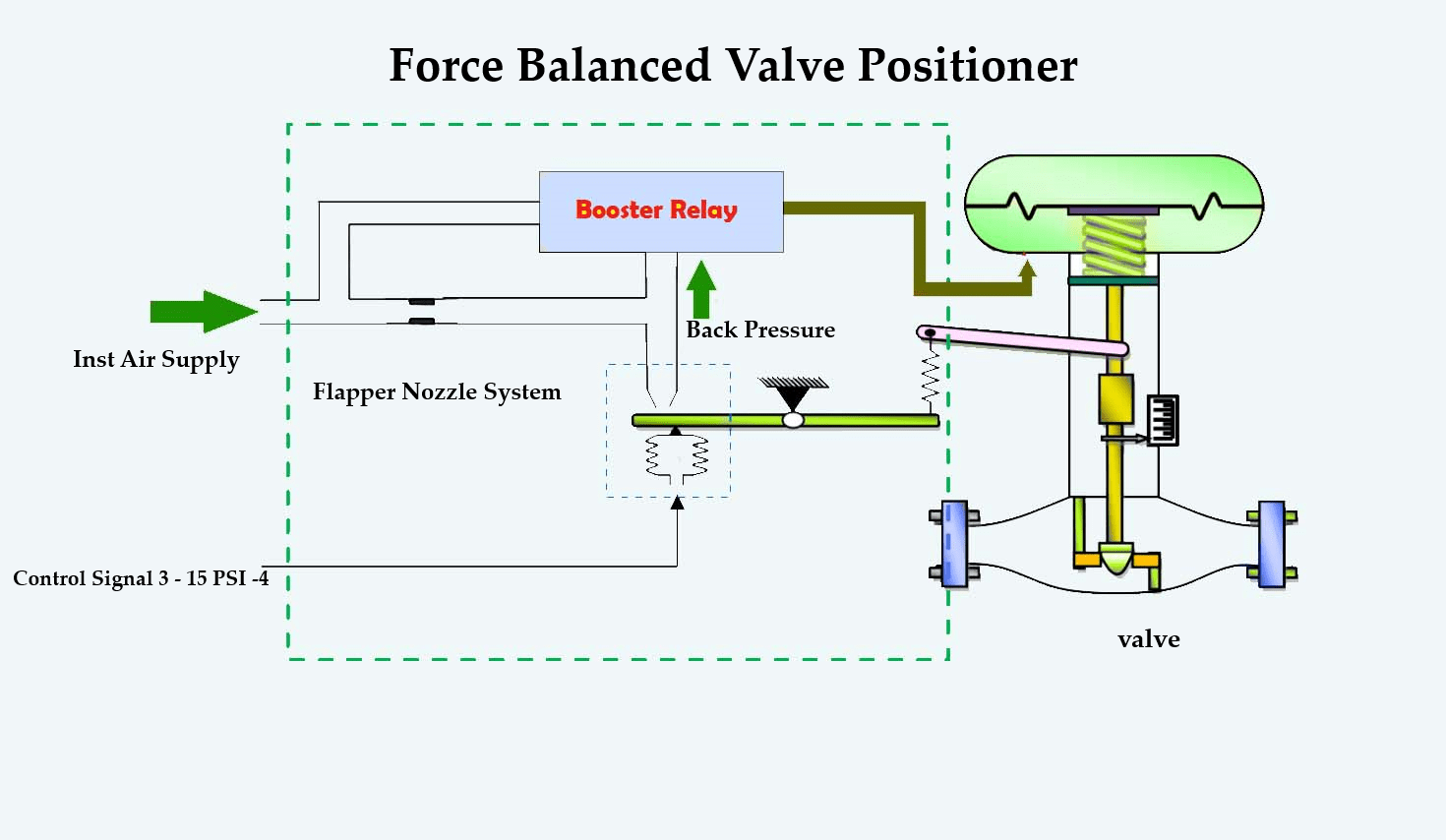
The figure shows a valve positioner. The valve positioner is a force-balanced device with a pneumatic module installed in a double-acting actuator for air-open action. working principle of electro-pneumatic positioner Stabilization is based on the balance of two forces; One is proportional to the instrument signal and the other is proportional to the shaft position.
The downward force is activated by the actuation of the signal pressure device on the diaphragm in the signal capsule. working principle of electro-pneumatic positioner Through the following arm and cam, the movement of the actuator shaft is transmitted to the upper end of the feedback spring, resulting in a change in tension in the feedback. Stems change position in spring.
The system is in equilibrium and when these opposing forces are properly balanced the shaft is in the position indicated by the instrument signal. If these opposing forces are not balanced, the balance will move up or down and change the output pressure and flow rate through the spool valve. working principle of electro-pneumatic positioner This will cause the piston to move until the tension of the feedback spring is directly opposite to the signal pressure of the tool.
The detailed sequence of positioner functions is as follows:
- Amplification of the instrument signal forces the instrument signal capsule and balance beam downward.
- This movement of the balance beam pulls the pilot valve spool down from its equilibrium position.
- It opens the pilot valve port and supplies air to port 1 and exhausts air from port 2.
- This causes the actuator piston to move upwards. Proportional to the valve position, the piston strikes upward until the force on the return spring increases sufficiently to counteract the force generated by the instrument signal capsule.
- At this point the balance beam and spool begin to return to the balance position.
- As the valve spool ports begin to close, the air flow rate into the actuator decreases.
- After the piston reaches the desired position, the feedback spring tension force is equal to the force developed on the instrument signal capsule.
- There is no air flow to the actuator until the balance beam and instrument signal capsule are in their equilibrium position and there is a change in the instrument signal.
- The proportional downward movement of the actuator piston and shaft is affected by the reduction of the device signal that modulates the described actions.
Control valve positioner assembly
A valve positioner has a very high gain amplifier – this can be pneumatic, electropneumatic, etc., and a feed back connection that detects the actual position of the valve.
The operation required is to close the valve. working principle of electro-pneumatic positioner The inlet pressure drops from the regulator to the nozzle. After the hole collapses, the flapper moves away from the tip and pressure. The diaphragm pressure drops and the valve begins to close. By rotating the cam clockwise the feed back arm moves upwards. This widens the beam, thereby increasing the back pressure at the tip until equilibrium can restored.
Changes in the cocking allow the signal from the controller to can placed directly into the diaphragm. working principle of electro-pneumatic positioner
Stabilizer advantage
- Net position
- Withstands large changes in forces acting on the plug
- Acute condition
- Eliminates friction and friction effects of the gland
- Eliminates the effect of large distances between valve and positioner
- Eliminates hysteria
When to place the positioner:
A stabilizer should can considered in the following situations:
- When precise valve positioning can required;
- To speed up valve response. The positioner uses high pressure and high air flow to adjust the position of the valve;
- To increase the specific actuator and valve closing pressure. working principle of electro-pneumatic positioner (to act as an amplifier);
- When the valve pressure drop at maximum operating flow rate exceeds 5 bar for single seated valves or 10 bar for double seated valves;
- To straighten the non-linear actuator; working principle of electro-pneumatic positioner
- The position of the plug may vary due to various differential pressures within the fluid;
- When controlling with a wide throttling range; And
- When handling sludge or solids in valve suspension.
Pneumatic valve positioner working principle
A pneumatic valve positioner is a device that operates on the force balance principle to position the control valve stem according to a pneumatic signal received from a controller or manual loading station, regardless of packing box friction, actuator hysteresis, or unbalanced forces on the valve plug. without doing Thus, working principle of electro-pneumatic positioner the stabilizer ensures reliable and accurate operation of the control valve.
Principle of operation
The valve positioner is a force balancing device that ensures the position of the plug is directly proportional to the controller output pressure. working principle of electro-pneumatic positioner The positioner actuator compares the control signal via the connector and feed back cam to the forces generated by the control valve stem and accordingly it feeds or bleeds air to the valve actuator.
The instrument wind signal can applied to the signal diaphragm. An increase in signal causes the diaphragm and flapper-connecting shaft to move to the right. The flapper-connecting shaft opens the supply flapper to admit supply pressure to an output connected to the actuator diaphragm. When the flapper connecting rod can turned to the right, the exhaust flapper can closed. The effect of the increasing signal is to increase the pressure on the actuator.
working principle of electro-pneumatic positioner This increased pressure on the actuator moves the valve stem downward and rotates the positioner lever clockwise. This clockwise rotation of the lever results in compression of the range spring by the cam. When the valve stem reaches the position indicated by the controller, the compression on the range spring will provide a balancing force, resulting in the closing of both flappers.
If the control signal can reduced, the force exerted by the signal diaphragm can also reduced and the force from the range spring pushes the flapper-connecting rod to the left, opening the exhaust flapper. working principle of electro-pneumatic positioner This causes a reduction in actuator diaphragm pressure and allows the valve stem to move upward until a new force balance can established.
Dynamic response and stabilization
Accuracy
MIL 8013 positioners, by direct comparison, are force balancing electro-pneumatic devices.
The controller provides valve stem position, dynamic feedback and matching with a DC output signal.
Accuracy cannot achieved with a transducer and pneumatic positioner combination.
Split-range controller
In addition, the stabilizer provides a precise means of dividing the controller output signal by a controller for continuous operation of two or more control valves. working principle of electro-pneumatic positioner
Corrosion resistant
This model of electropneumatic valve positioners is therefore suitable for very corrosive environments
Bleeding from an internal node. It provides continuous purification.
Direct action and inverse action
Stabilizers are available for direct action (increasing the electrical signal increases the output
pressure) or reverse action (increasing electrical signal decreases output pressure) direct (air-
close) or reverse (to open with air) actuators, diaphragm or cylinder type.
Read More>>>> How does common rail direct injection work
Vibration resistance
MIL’s nozzle design provides a detection system that can not affected or damaged by valve vibrations.working principle of electro-pneumatic positioner Zero and period shifts are essentially independent of resonance.


