Oil pump Definition
Types of Oil Pumps – Definition, Working, Diagram, Working Principle [Complete Guide]:- Oil siphon is referred to as a mechanical device which is used for the purpose of injecting oil directly into the motor parts. working principle of rotor oil pump with diagram it finds an application in protecting parts from wear in bearings, camshafts and cylinders. These types are known to be one of the most important components possible to the motor oil structure, and should not be damaged or worn out. Otherwise there will be a breakdown.
The components of an oil siphon in a car are:
- Under the influence of pressure, the oil moves into the main components of the motor.
- Easier development of motor oil around the motor.
- Coordinates oil development through demonstrations in various sectors.
- Supply helps to convert hot oil into cold oil.
- Maintains uninterrupted circulation of oil inside the motor.
working principle of rotor oil pump with diagram
- An oil siphon is essential in a motor for greasing as there may be a need for greasing during running. An oil siphon is a device usually operated from the drive rod and begins to draw oil as soon as the motor is started. working principle of rotor oil pump with diagram Oil injectors are used in some motors that do not use oil, such as two-strokes.
- The oil can cooled before passing through the galleries to reach the engine working parts and return to the sump. Oil appears to applied to the walls of all individual chamber seals found within the chamber and to the separator rings in the chamber. This prevents dense air from moving out of the chambers, increasing the overall efficiency of the engine.
- Specifically, for every minute (rpm) it can move it can increase by 55-65 psi, an engine known to increase oil pressure by 10 psi. The pressure set in the crankshaft journal with the bearing varies from a setting of 50-60 psi, and then is significantly higher than the relief valve on any kind of relative pump that can reach hundreds of psi. One time.
- High oil pressure in the front or main engine can cause the oil plugs to explode. working principle of rotor oil pump with diagram When the engine is cold, high oil pressure means high pressure caused by the design of the engine.
- This causes the motor parts to wobble from the top of the motor to the cam transporter header. As a result, these lead to a decrease in oil in the upper body. If the crown comes out of the cylinder, low tension can cause problems with the liner cylinder. Low oil pressure can also seize the drive rod and associated shaft.
Low oil tension can brought about by:
- Low oil pressure can attributed to a cracked or broken oil siphon or a broken strain relief valve spring.
- The motor does not have enough oil, or any other type of oil. The main bearings can gone.
- Disruption or stoppage of oil exhibition
Types of oil pipelines
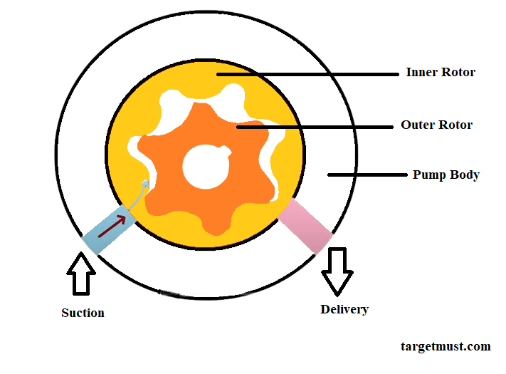
1.Rotor oil pump
A rotor oil pump is a type of oil siphon, also known as a gerotor siphon. It can seen that material can present locally where it turns from the inside to the outside rotor. The inside rotor has fewer turns than the outside rotor, and can installed at a considerable angle to the outside rotor. It is responsible for providing power to the outer rotor to spin the rotor at about 80% of the speed of the inner rotor.
Pumping like a bellows involves a movement created for the purpose of drawing oil, which can brought to the inlet port and pushed towards the outlet port. It is a so-called rotor-type oil pump that can meet particularly tight tolerances for the purpose of optimal pumping stability. This type of pump is located inside the crankcase.
-
Front Cover Oil Pump:
The oil pump on the front cover can also known as the internal or external pump. The siphon rotates at the same rpm as the motor. Therefore, more pressure can generated on the outside of the gears than in a camshaft or bulkhead driven siphon. The introduction page mentions a type of oil siphon that can used on almost all overhead cam motors and can also found on later model pushrod motors.
This type of situation occurs when the engine detects that it is cold and starts for the first time. It is responsible for slowing the flow of oil.
-
Double Gear Pump: (Oil Pump Type)
A double gear pump can an external pump called a pump, commonly known by its other name as a double gear pump. This type of pump can said to the one found inside the oil pan at the bottom of the engine. It pumps the oil using two intermittent gears. For example, you should know that the crankshaft, camshaft or distributor shaft can considered one of the most commonly connected shafts responsible for driving the first gear.
The teeth of the gears catch the oil and pull it around the outer parts from the pickup tube channel to the power source.
-
Common Failure in Oil Pump: (Types of Oil Pumps)
The main function of this type of pump is to foul the commonly found oil siphon, which is a type of deep damage to the vehicle. Side effects. These types of drivers can known as motorists who experience engine trouble any time the oil light marker on the vehicle’s dashboard comes on, indicating that there is a problem. Disappointing side effects of Oil Siphon include:
Low Oil Pressure: Known as a malfunction, this could be a bad oil pump that cannot pump oil through the system very efficiently. Low oil pressure can cause engine damage. However, as mentioned earlier in this post, there are different indicators of low oil pressure.
When the siphon is in good condition, the oil progress is steady and the motor is at normal temperature. If the progress of motor oil slows or stops, parts can lubricated by hot oil that can not allowed to flow.
Applications of different types of industrial pipelines in oil and gas industry
In the oil and gas business, various industrial pipelines can used for fluid transfer. Pipelines used in the oil and gas industry can divided into six groups based on their design and construction:
- Centrifugal pump
- Reciprocating plunger pump
- Progressive cavity pump
- Gear pump
- Diaphragm pump
- Metering pump
-
Centrifugal pump
The most common type of pump used in the oil and gas business is the centrifugal pump. Centrifugal pumps use centrifugal force to draw fluid into the pump’s intake and force it through the discharge section. Discharge flow control valves control pump flow. Single-stage radiating siphons can basically used to transfer low-consistency fluids that require high flow rates. These tubes can typically used as one component of a larger siphon found in networks and other radiation siphons.
-
Reciprocating plunger pump
Oil and gas businesses can generally known to go with plunger pumps, making these the most common industrial pumps. Plunger pumps use the reciprocating motion of a plunger and piston to force fluid through a piping system in an enclosed cylinder. Un-cloaker siphons require more stable support than diffusive siphons due to the design of the moving parts. These have a quieter operation than external siphons.
-
Progressive sump pump
Advances use various techniques such as siphoning or directing a current of liquid through small, fixed-sized, discrete cavities whose rotor rotates continuously. Medium bore siphons can generally used in highly concentrated applications or where mixing of the siphoned liquid can not required.
The structural pressure will determined as the stream rate, which can fairly constant to maintain a given flow rate. At higher voltages, current drift is normal. The relief valve is an important component of the ever-evolving pit siphon output channeling structure, as it protects the siphon and funneling structure from over pressurization.
-
Diaphragm pump
Diaphragm pumps can said to be among the most adaptable oil and siphons in the business, and they move fluid through valves and discharge through a belly. There are various working instructions for this type of siphon. working principle of rotor oil pump with diagram One of these is expansion due to tension in vacuum and volume decrease.
Some diaphragm pumps found in oil refineries can specially installed for high volume fluid transfer operations. working principle of rotor oil pump with diagram They require much less maintenance in terms of cost and can compared to positive displacement pumps because they have lower speeds.
Gastric siphons, on the other hand, are sensitive to ‘winks’ – low pressure levels within the structure that inhibit siphon movements. You should know that there are similar explanations for this, that they are not suitable for the purpose of stopping operations or that they have a significant distance for siphoning and that they are mostly and do not meet the requirements. High pressure conditions.
Read More>>>> What is the working pressure of a gear pump
-
Gear pump
A gear pump finds use in pumping for the purpose of displacing a fluid using gear meshing. Gear pumps find application in moving various industrial fluids.
External gear pumps using two XTEs.


