How does a gear pump work?
Gear pumps use the action of rotating teeth or gears to move fluids. The rotating element forms a fluid seal with the pump body and creates suction at the pump inlet. What is the working pressure of a gear pump Fluid drawn into the pump is trapped in the cavities of its rotating gears and transferred to the discharge. There are two basic designs of gear tubes: external and internal.
What is the working pressure of a gear pump
In the external perfection tools pumps. the standard operating stress can limited to 210 bars( 21,000 kPa) and a most rotational haste of 3,000 rpm. Still, some directors have finagled gear pumps. that surpass these thresholds both pressure and speed. Yet, it’s important to admit that similar pumps tend to induce. further noise and need unique safety measures. Gear pumps are an essential element in colorful diligence, from hydraulic. What is the working pressure of a gear pump systems to oil painting refineries and chemical processing shops. They play a vital part in pumping and transferring. fluids with perfection and effectiveness. But, one pivotal aspect that determines.
Their performance is the working pressure they can handle. Understanding the working pressure of a gear pump is essential for icing. its optimal operation and precluding implicit damage or failures. explore how it affects gear pump performance and bandy factors. that influence this critical parameter. What is the working pressure of a gear pump Whether you’re a mechanical mastermind or simply curious about. the inner workings of these important machines, join us on this instructional. trip to unravel the mystifications behind gear pump working pressures.
External gear pump
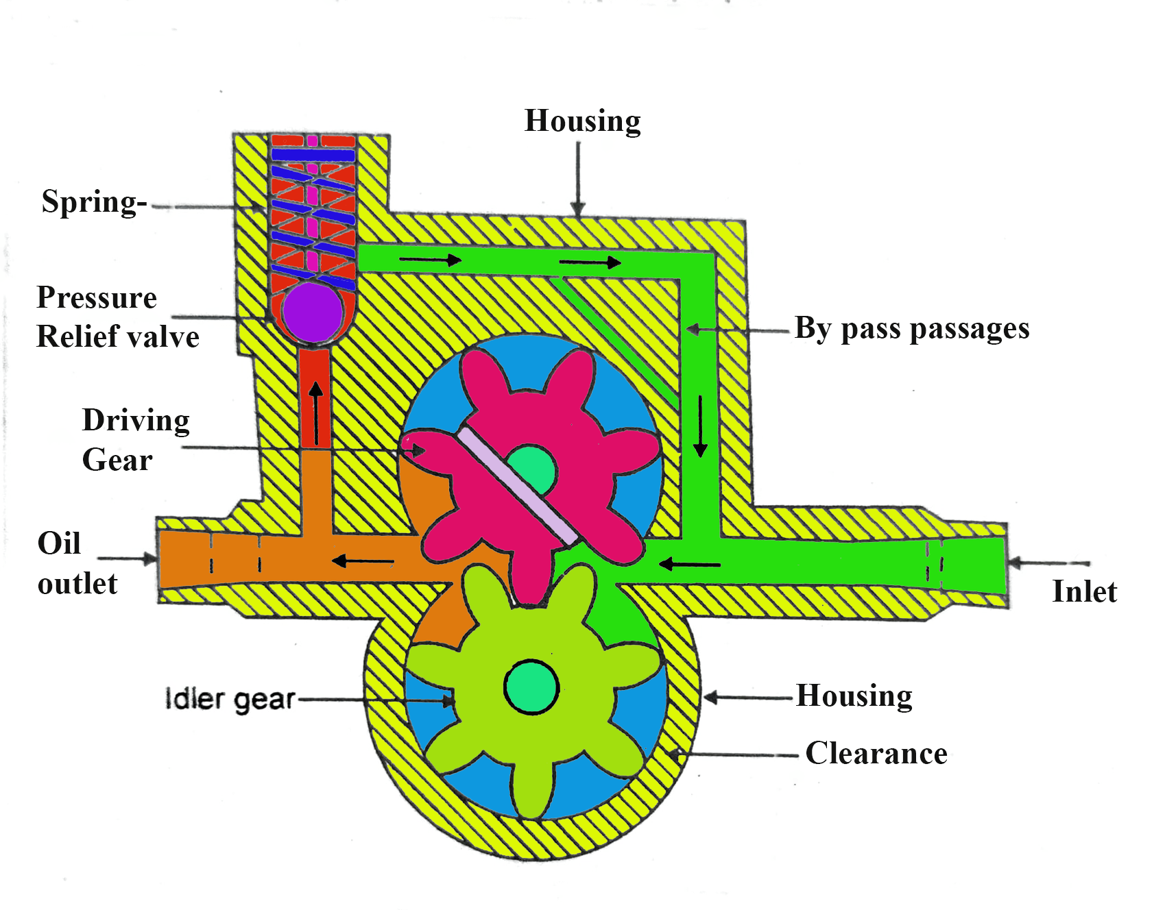
An outside tools pump consists of two equal, interlocking gears supported via separate shafts. Typically, one gear is driven by the motor, which drives the other gear (the idler). In some cases, both shafts may be driven by a motor. The shaft is supported by bearings on each side of the casing.
- As the gears come out of the mesh on the inlet side of the pump, they form an expanded volume. What is the working pressure of a gear pump As the gear rotates against the pump casing fluid flows into the cavities and is trapped by the gear teeth.
- Entrapped fluid is transported around the casing from inlet to outlet.
- As the gear teeth on the discharge side of the pump engage, the volume is reduced and the liquid is discharged under pressure.
There is no fluid transfer back through the hubs between the gears because they are linked together. What is the working pressure of a gear pump Close tolerances between the gears and casing allow the pump to create suction at the inlet and prevent fluid from leaking back from the discharge side (although leakage is more common with low-viscosity fluids).
Internal gear pump
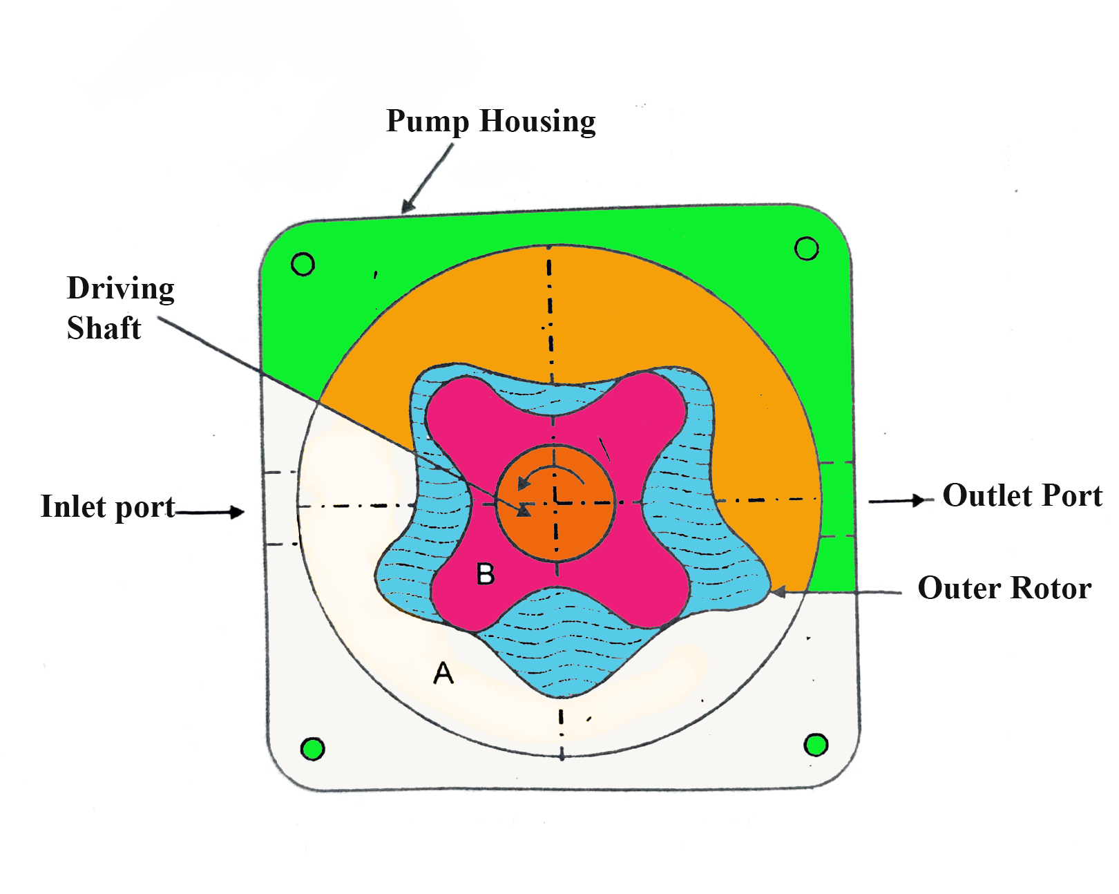
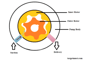
An internal gear pump works on the same principle but has two interlocking gears of different sizes, one rotating inside the other. The large gear (rotor) is an internal gear, that is, its teeth extend inward. A small external gear (idler – only the rotor can driven) can mounted off-centre within it. It can designed to engage the rotor so that the gear teeth engage in one step. A pinion and bushing attached to the pump casing stabilizes the idler. What is the working pressure of a gear pump A standard crescent-shaped partition or spacer fills the void created by the idler’s off-center mounting position and acts as a seal between the inlet and outlet ports.
- As the gears come out of the mesh on the inlet side of the pump, they form an expanded volume. As the gear rotates against the pump casing and partition the fluid flows into the cavities and can trapped by the gear teeth.
- Entrapped fluid can transported around the casing from inlet to outlet.
- As the gear teeth on the discharge side of the pump engage, What is the working pressure of a gear pump the volume can reduced and the liquid can discharged under pressure.
What are the main features and advantages of gear pump?
Gear pumps are compact and simple with few moving parts. They cannot match the pressure generated by the flow rate of reciprocating pumps or centrifugal pumps, but provide higher pressure and efficiency than vane or lobe pumps. What is the working pressure of a gear pump Gear pumps are particularly suitable for pumping oil and other high viscosity liquids.
In both designs, external gear pumps are able to maintain higher pressures (up to 3000 psi) and flow rates due to more rigid shaft supports and closer tolerances. Internal gear pumps have excellent suction capabilities and are suitable for high viscosity fluids, although their effective operating range is from 1cP to 1,000,000cP. Because the output can directly proportional to the rotational speed, gear pumps can commonly used for metering and mixing operations.
What is the working pressure of a gear pump Gear pumps can designed to handle aggressive fluids. They can usually made of cast iron or stainless steel, new alloys and compounds allow pumps to handle corrosive liquids such as sulfuric acid, sodium hypochlorite, ferric chloride and sodium hydroxide.
External gear pumps can used in hydraulic power applications, typically in vehicles, lifting machines and mobile plant equipment. Driving the gear pump in reverse, using oil pumped from elsewhere in the system (usually by a tandem pump on the engine), creates a hydraulic motor. What is the working pressure of a gear pump It is especially useful for providing power in areas where electrical equipment is bulky, expensive or inconvenient. For example, tractors rely on engine-driven external gear pumps to operate their services.
What are the limitations of gear pumps?
Gear pumps are self-priming and dry-lifting, although their priming characteristics improve when the gears wet. Gears should lubricated with pumped fluid and not run dry for long periods of time. What is the working pressure of a gear pump Some gear pump designs can operated in both directions, for example, the same pump can used to load and unload a vessel.
The close tolerances between the gears and casing make these types of pumps prone to wear, especially when used with abrasive fluids or feeds containing entrained solids. What is the working pressure of a gear pump However, some designs of gear pumps, especially internal variants, allow solids to handled. External gear pumps have four bearings and tighter tolerances on the pumped medium, so they are less suitable for handling abrasive fluids. What is the working pressure of a gear pump Internal gear pumps are very robust with only one bearing (sometimes two) moving in fluid. A gear pump should always install a strainer on the suction side to protect against large, harmful, solids.
General notes on gear units
Over the past few decades, a large number of pump concepts have emerged, and selecting the appropriate pump for a particular viscous fluid application has become an important consideration. In general, a particular pump may work efficiently for one application but be unsuitable for others. What is the working pressure of a gear pump To aid in the selection and design of pumps, various charts and tables have developed to show the efficiency and effectiveness of different pump types based on specific speeds and other parameters.
In addition to these theoretical considerations of effectiveness and suitability of pressure ranges, other important benefits such as reliability, availability, overall performance and functionality should respected. Over positive displacement pumps, gear pumps have some significant advantages.
Design and function
As the gears come out of mesh, they create an expanded volume on the suction side of the gear pump. Fluid flows into the cavity of the gear teeth and trapped by the gear teeth as they rotate. Fluid can also get into the pockets on the inside of the case between the teeth and the case. What is the working pressure of a gear pump This small flow does not pass through the gears. The gear mesh forces fluid to flow through the discharge port under pressure.
In gear pumps, the running clearance between the gear face, gear tooth crest, and housing creates relatively constant losses at any pumped volume at a given pressure. This means volumetric efficiency can poor at low speeds and low flows, so gear pumps should operated close to their maximum rated speed.
Function
In addition, pressure pulses induced by the transient discharge of the gear pump should measured to verify trouble-free operation of the gear pump. Pressure pulses or waves (suction or discharge) generated by the interaction of pumping dynamics with the dynamic behavior of suction and discharge piping systems. The presence of a pressure pulse will cause pressure fluctuations and hence fluctuating flow in the gear inter-tooth gap. What is the working pressure of a gear pump If the minimum pressure pulse point coincides with the expansion phase when the lateral flow zone opens, it may cause some malfunction or poor performance.
In a gear pump, the frictional torque and consequently the pump operation and required power can affected by fluid temperature and operating pressure as well as pump speed. When the pressure difference is large, the frictional torque first decreases and then increases with the increase in pump speed. What is the working pressure of a gear pump For large pressure differential, frictional torque may increase as fluid temperature increases in the low pump speed region, but the opposite trend may occur in the high pump speed region.
Transient conduction and cavitation
When a gear pump operates with a relatively low suction pressure (for example, when liquid from a tank is at a low level), the pressure in the suction pipe and chamber approaches the vapor pressure, and cavitation from the gear meshing occurs above. May be towards area.
Another common operational problem is cavitation during transient operation. What is the working pressure of a gear pump A common cause of cavitation is insufficient flow in enlarged tooth surfaces. In many of these subjects, theoretical or operational studies, consideration should can given to the amount of tooth-tooth formation in the roots of the drive and driven gears. Compressible flow in and out of these blocks plays an important role in the cavitation and transient process.
Read More>>>> Working principle of rotor oil pump
Production and display
Gear pumps typically come in single or double (two sets of gears) pump configurations with various gears such as spur, helical, and herringbone gears. Helical and herringbone gears generally provide smoother running than spur gears, although all gear types are relatively smooth. What is the working pressure of a gear pump Straight spur gears are easy to cut and can commonly use. Helical and herringbone gears run more quietly, but are more expensive. These can generally used in large-capacity gear pumps.
The amount of displacement of a gear pump can directly affected by the gear tooth profile. What is the working pressure of a gear pump Because the involute gear tooth profile is easy to manufacture and uses the technology in power transmission gears, this profile can commonly used for low-cost gear pumps. In an involute gear, the profile of the teeth covers a circle.

